Turntable Traction Drive Integration Guide
This guide is designed to help scenic designers and technical directors integrate the Turntable Traction Drive into their sets.
![]() Before Proceeding, make sure you have read and understood the SAFETY section of the documentation.
Before Proceeding, make sure you have read and understood the SAFETY section of the documentation.
![]() Before Proceeding, make sure you have read and understood the Limitations section of the documentation.
Before Proceeding, make sure you have read and understood the Limitations section of the documentation.
Turntable Integration
The Turntable Traction Drive applies significant forces to the side of the turntable where it makes contact. This requires the following considerations:
- The Turntable Traction Drive should not be pressed against a surface which will bow or deflect under pressure. Ideally you'd want a 3" wide rigid band that the turntable can drive against. In practice we've found that the drive wheels can get plenty of traction when applied against the edge of a 1.5" laminated plywood floor.
- The drive wheels of the traction drive may cause maring or discoloration of surface finishes. You may need to apply a protective coating to traction surfaces if they are visible to the audience.
- The drive wheels of the traction drive apply force to just one side of a turntable. To keep the turntable centered on its rollers your centering device must be sufficiently rigid (and well lubricated) to counter this force.
Critical Dimensions
The two key factors when determining if this machine will work with your turntable are diameter and mass. At present we don't have sufficient information to give guidance about maximum turntable mass. Except to say that we had no difficulty moving a 23' turntable with a 2-story wood and steel "castle" on it.
| Dimension | Value |
|---|---|
| Minimum Turntable Diameter | 6' |
| Maximum Turntable Diameter | 23' Demonstrated (Maximum Unknown) |
If the diameter of your turntable is too large you may have difficulty running it fast enough with the as-designed gearing. If this is the case you have two options:
- You may increase the diameter of your drive rollers up to 12" in diameter (this size is quite extreme consider 8"). Increasing the diameter of the drive rollers will cause you to suffer a substantial loss of starting torque. The advantage is increased speed at your motor's native frequency without an increase in chain noise.
- You may decide to overdrive your motor beyond 60Hz. Many VFDs will let you run the motor up to 400Hz, at this speed you would likely damage your gearbox, motor and chain drive. Many motors will be perfectly happy to run faster than 60Hz with reduced duty cycle. Consult your motor and gearbox documentation to determine the maximum safe operating speed of your Turntable Traction Drive.
Another critical factor is the height of the traction-bearing surface relative the bottom of the turntable traction drive. The vertical position of the drive wheels is adjustable, but is ultimately constrined by the spacing between the drive sprockets. That said drive wheels have about 4" of vertical adjustability.
| Dimension | Value |
|---|---|
| Minimum Traction Surface Width | 1.5" |
| Maximum Traction Surface Width | 3" (Drive Roller Width) |
| Lowest Possible Traction Surface | 3.25" to 4.75" from the bottom of the machine |
| Highest Possible Traction Surface | 5.75" to 7.25" from the bottom of the machine |
If the traction surface of your turntable is too high, it may be neccesary to raise the machine so that it contacts the correct portion of the turntable. Conversely, it may be neccesary to mount your traction drive below the stage if your dive surface is too low.
Traction Pressure
The available tractive force of the Turntable Traction Drive is related to the pressure applied by the rollers against the traction surface. In other words, it's not sufficient to place the Turntable Traction Drive next to a turntable, it must be pressed firmly against the side of it.
This "preload" pressure may be created via two integration schemes:
Ratchet Straps
In testing the Turntable Traction Drive we observed that we could apply ample force between the drive wheels and the turntable simply by connecting ratchet straps between the machine chassis and the carrier wheels of the turntable.
This system has several advantages over the Pusher Spring system:
- Rachet straps are plentiful and easy to inspect.
- The have some natural stretch to them, allowing for eccentricity of the turntable.
- They are easy to remove and reattach, simplifying maintenance activities.
- Rachet straps don't create metal-on-metal noise as they stretch.
For these reasons ratchet straps are prefered mecahnism for integration.
To attach the turntable via rachet straps:
- Ensure that the Turntable Traction Drive is evenly supported and that you have strong material under the lag-bolt slots.
- Connect the left and right sides between the rear of the side-panels and a suitably strong tie-down point on or near your turntable.
- Evenly tension the two belts such that drive wheels are in good contact with the turntable.
- Lag-bolt the machine down to the supporting surface loosely. (Such that the machine may become detached from the turntable, but may not be flung away from it.)
Pusher Springs
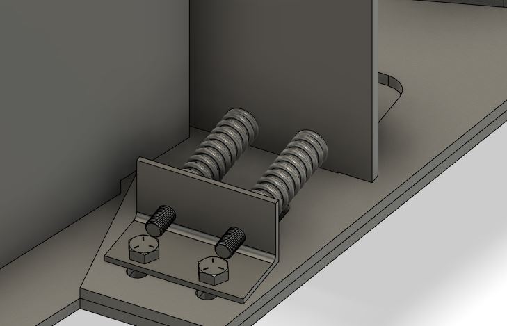
The design calls for the use of four pusher springs which ride on 5/16" guide bolts. These pusher springs push the turntable forward, away from two L-iron brackets anchored firmly to the deck. This mechanism allows for approximately 1.8" of eccentricity in the turntable circumference while applying around 200 lbs of force.
To install the pusher springs follow these instructions:
- Ensure that the Turntable Traction Drive is evenly supported and that you have strong material under the lag-bolt slots.
- Weld hex-heads the 5/16" partially-threaded guide bolts into the four holes provided in the pusher plates. The bolts should face backwards with the bolt heads resting on the interior faces of the pusher plates.
- Slide the pusher springs over the guide bolts.
- Pass the guide bolts into holes drilled in the L-iron.
- Using 5/16" lock nuts, compress the pusher springs between the L-Iron and the pusher plates.
- Using lag-bolts, bolt the L-iron to the supporting surface. Make sure the lag-bolts pass through the slots on the bottom plate.
- Loosen the 5/16" lock nuts such that the springs expand between staticaly mounted L-iron and the movable Turntable Traction Drive.
Note: In the pusher spring rendering there is insufficent clearance between the guide-bolts and the lag-bolts. This has been remedied by raising the holes in the pusher plate.
Integration Checklist
To help ensure safe operation of this Turntable Traction Drive please ensure the following REQUIRED conditions have been met:
| Requirement | Complete |
|---|---|
| Technical Director/Integrator must read and understand the safety section of this documentation. | |
| Turntable Traction Drive chassis grounded to motor frame | |
| Motor frame grounded to VFD | |
| Turntable Traction Drive is fully enclosed in a secure area | |
| Drive-wheel interface points are fully enclosed | |
| Turntable hard-scenery elements don't create opportunities for shearing or crushing | |
| Emergency stop button located within 6' of Turntable Traction Drive | |
| Turntable fitted with an external parking brake (or other disablement device.) |
VFD Configuration
DURApulse GS23-22P0 Configuration
Note: These notes are only really useful for the DURApulse GS23. If you're using another VFD consult your documentation.
When configured correctly we desire the following outcome:
- To tell the turntable to run forward short
DCMtoDI1/FWD. - To tell the turntable to run in revers short
DCMtoDI2/REV. - To enter Safe Torque Off
STOinterrupt short between+24 Vand eitherSTO1orSTO2
DURApulse GS23 Parameters
| Parameter | Value | Notes |
|---|---|---|
P02.00 |
2 |
2-Wire Configuration |
P01.10 |
60 |
Output Frequency Upper Limit |
P01.12 |
1 |
Acceleration Time 1 |
P01.13 |
1 |
Deceleration Time 1 |
P06.12 |
?? | Current Limit 0-250% |
Hitachi L100 Configuration
Note: These notes are only really useful for the Hitachi L-100. If you're using another VFD consult your documentation.
P24 provides a 24V field reference voltage for use when powering the Control Terminals.
When configured correctly we desire the following outcome:
- To tell the turntable to run forward short
P24toPIN 1. - To tell the turntable to run in revers short
P24toPIN 2.
Hitachi L100 Parameters
| Parameter | Value | Notes |
|---|---|---|
a01 |
00 |
00=Keypad/Potentiometer, 01=Control Terminals, 02=F01 Settings |
a02 |
02 |
01=Control Terminals, 02=Keypad Run Key |
a02 |
02 |
01=Control Terminals, 02=Keypad Run Key |
a61 |
60 |
Set a hard limit on the output frequency of the VFD to never overdrive the motor. |
a04 |
60 |
Set the "Base" Frequency. (The frequency at which the VFD emits full voltage) |
a05 |
60 |
Set the "Max" Frequency (The frequency allowed during manual opeation) |
a97 |
00 |
Set the Acceleration Curve: 00=Linear, 01=S-Curve |
a97 |
00 |
Set the Deceleration Curve: 00=Linear, 01=S-Curve |
c01 |
00 |
Configure Terminal 1: 00=Run Forward |
c02 |
01 |
Configure Terminal 2: 01=Run Reverse |
f01 |
nn |
Set the target frequency |
f02 |
nn |
Set the acceleration time (The number of seconds it should take to get spin-up from 0Hz to f01Hz) |
f03 |
nn |
Set the deceleration time (The number of seconds it should take to get spin-down from f01Hz to 0Hz) |