This is my design for a Turntable Traction Drive. It's meant to turn a large theatrical turntable covered in sets and actors in a safe reliable way. It can be built for less than $3000 USD.
I was inspired to take on this project by Alan Hendrickson's chain-driven design featured in Technical Designs Solutions for Theatre Volume 2 (Sammler/Harvey 2002). His design shows how a chain drive can rotate a turntable. I was interested in designing an easier-to-integrate "bolt-on" solution.
Table of Contents
- Safety
- Design Document
- Parts Sourcing Guide
- Assembly Guide
- Integration Guide
- Operation Guide
- Bill of Materials
- Wiring Guide
- License
Turntable Traction Drive Safety and Liability
As it's intended use involves live actors on a rotating stage, the safety of the Turntable Traction Drive must be considered seriously. But before we dig into a risk assesment understand this:
I am not an engineer. I write software for a living and am not formally trained to assess safety risks. As such, any risk assesment made here should not be considered comprehensive.
In undertaking this project, and making it publicly available, it behooves me to draw attention to this fact, as well as to to state clearly that I don't guarantee that this design works as intended, and I am not liable for any harm resulting from your use of this design.
Liability
This design is available for use under the Creative Commons Attribution 4.0 International license. By using this design you agree to the terms of this license.
The license includes the following language, which you should read:
Section 5 -- Disclaimer of Warranties and Limitation of Liability.

  a. UNLESS OTHERWISE SEPARATELY UNDERTAKEN BY THE LICENSOR, TO THE
     EXTENT POSSIBLE, THE LICENSOR OFFERS THE LICENSED MATERIAL AS-IS
     AND AS-AVAILABLE, AND MAKES NO REPRESENTATIONS OR WARRANTIES OF
     ANY KIND CONCERNING THE LICENSED MATERIAL, WHETHER EXPRESS,
     IMPLIED, STATUTORY, OR OTHER. THIS INCLUDES, WITHOUT LIMITATION,
     WARRANTIES OF TITLE, MERCHANTABILITY, FITNESS FOR A PARTICULAR
     PURPOSE, NON-INFRINGEMENT, ABSENCE OF LATENT OR OTHER DEFECTS,
     ACCURACY, OR THE PRESENCE OR ABSENCE OF ERRORS, WHETHER OR NOT
     KNOWN OR DISCOVERABLE. WHERE DISCLAIMERS OF WARRANTIES ARE NOT
     ALLOWED IN FULL OR IN PART, THIS DISCLAIMER MAY NOT APPLY TO YOU.

  b. TO THE EXTENT POSSIBLE, IN NO EVENT WILL THE LICENSOR BE LIABLE
     TO YOU ON ANY LEGAL THEORY (INCLUDING, WITHOUT LIMITATION,
     NEGLIGENCE) OR OTHERWISE FOR ANY DIRECT, SPECIAL, INDIRECT,
     INCIDENTAL, CONSEQUENTIAL, PUNITIVE, EXEMPLARY, OR OTHER LOSSES,
     COSTS, EXPENSES, OR DAMAGES ARISING OUT OF THIS PUBLIC LICENSE OR
     USE OF THE LICENSED MATERIAL, EVEN IF THE LICENSOR HAS BEEN
     ADVISED OF THE POSSIBILITY OF SUCH LOSSES, COSTS, EXPENSES, OR
     DAMAGES. WHERE A LIMITATION OF LIABILITY IS NOT ALLOWED IN FULL OR
     IN PART, THIS LIMITATION MAY NOT APPLY TO YOU.
In plain language: I don't guarantee that this design works as intended, and I am not liable for any harm resulting from your use of this design.
Limitations
The Turntable Traction Drive has the following known limitations/deficiencies:
- No Brake: The Turntable Traction Drive does not provide built-in braking. (This may be remedied by using a motor configuration with a power-off brake.) In practice this means that when the drive is not rotating the turntable is only kept in place by two things: The inertia of the turntable itself, and the friction in the chain and gearbox system of the Turntable Traction Drive. For massive (high-mass) turntables with substantial loss due to friction this is not a problem, as the turntable will tend to stay put. For low-mass or low-friction turntables it may be neccessary to use an external braking mechanism to keep the turntable from free-rotation when the drive is not rotating.
- Insufficient Current Limiting Capabilities: Ideally we would like to set a current limit at various stages of operation such that the inverter trips when there is an unexpected spike in current. The Hitachi L100-007NFU does not have sufficiently granular current-limit controls.
- Open Loop: The Turntable Traction Drive is a machine for rotating a turntable. It is not a machine for accurately "positioning" a turntable. As such this machine's utility in precise motion control applications may be limited.
Key Safety Principals
![]() The Turntable Traction Drive is a powerful machine. Using it should not be taken lightly. Caution and care must be taken in every integration to ensure that safe operating parameters are configured.
The Turntable Traction Drive is a powerful machine. Using it should not be taken lightly. Caution and care must be taken in every integration to ensure that safe operating parameters are configured.
A turntable may pose a hazard on set even when operated manually by backstage technicians, however, unlike backstage technicians this machine has no brain. It doesn't know to stop because a piece of scenery is late during a scene-shift. It is not context-aware. Also, unlike a backstage technician, under the right circumstances this machine can summon inhuman amounts of torque.
![]() Due to its power and remoteness this machine is not designed as part of an automation system. Rather, it is intended to be manually operated by a user with a clear view of the turntable.
Due to its power and remoteness this machine is not designed as part of an automation system. Rather, it is intended to be manually operated by a user with a clear view of the turntable.
The Turntable Traction Drive has exposed moving parts and therefore poses some first-hand risk of injury to operators. However, when attached to a turntable new hazards may appear.
![]() A scenic turntable creates risks of injury independant of the drive mechanism. Take care to evaluate the risks not just from the Turntable Traction Drive, but from the system as a whole.
A scenic turntable creates risks of injury independant of the drive mechanism. Take care to evaluate the risks not just from the Turntable Traction Drive, but from the system as a whole.
Risk Management
As some risk is unavoidable, my analysis will focus on mitigation strategies. Any requirement layed out in this section must be specifically required in either the Integration Checklist or Operations Checklist.
| Risk | Mitigation Strategy |
|---|---|
| Risk of electrical shock |
Requirements: Ground VFD appropriately to input mains. Ground motor appropriately to VFD. Ground chassis appropriately to the motor chassis. |
| Pinching hazards from exposed rotating machine parts. |
Requirement: Turntable Traction Drive must be in a fully enclosed secure area during operation. |
| Pinching/Crushing hazards between traction wheels and turntable edge. |
Requirement: Interface between the turntable and the traction drive must be fully enclosed during operation. |
| Risk of unexpected start |
Requirement: Enable Unattended Start Protection in VFD by setting c04 to 13 and short P24 to PIN 4Disconnect power from the system prior to maintenance. |
| Risk of fall during normal operation |
Requirements: Rehearse with onstage personel in order to find safe speeds and acceleration values. Do not deviate from these values without notice. |
| Risk of fall due to sudden acceleration |
Requirement: Use conservative acceleration/deceleration values when configuring VFD. (For Hitachi L-100 see settings f01, f02, and f03) |
| Risk of fall due to overspeed |
Requirement: Set a conservative hard frequency limit in your VFD configuration. (For Hitachi L-100 see settting a61) |
| Risk of crushing |
Requirement Where possible tune-narrowly the current limiting features of your VFD. (For the Hitachi L-100 this configuration may be limited.) |
| Risk of crushing because of external scenery-based crush points. |
Requirements: Turntables must maintain a raidal safety margin sufficient to prevent a person from being caught between a rotating piece of scenery and any adjacent piece of scenery. Emergency Stop button must located near the turntable. Cast and crew must be trained on the location of the Emergency Stop button. |
| Risk of entanglement |
Requirements: Operator must have a clear view of the turntable. Emergency Stop button must located near the turntable. Cast and crew must be trained on the location of the Emergency Stop button. |
| Risk of slipping on a free-rotating turntable |
Requirement A parking brake (or other disablement device) must be employed to prevent the turntable from turning when the Turntable Traction Drive is not in use. All on-stage personel must be instructed on the free-rotating-nature of the turntable. |
| Risk of operator/integrator ignorance |
Requirements: All safety requirements and warnings must be clearly printed on a label applied to the machine. Documentation must be made available. |
| Risk of structural collapse on turntable |
Requirement: Ensure that all scenery is constructed such that it can absorb tortional load such as might result from a sudden change in rotational speed. |
Turntable Traction Drive Design
Staples Players was looking for a way to add some automation and motion to its production of Disney's Descendants The Musical. I was interested in creating a solution which could be applied generically to any of the typical turntable configurations they use.
I decided to make a drive unit to rotate a turntable by applying a traction wheel against the edge of the table. Such a device would be easy to integrate in most sets where the turntable sits on top of the stage floor.
Mechanical Considerations
Using drive wheels to turn a turntable seemed pretty straight forward. I'm pretty sure I've seen carnival rides driven in this manner. As a gut-check I did a bit of marketplace research and found that such devices do exist.
My first idea was to use a motor with a gear reduction and a triangular chain configuration. The friction wheels would be pneumatic tires. The idea was that an idler would pull the chain away from the contact-point of the turntable and allow for easy tensioning of the chain system. However, preliminary research indicated two things: First, chains don't like to be run horizontally they prefer to run vertically. Second, a triangular configuation would result in an uneven distribution of power between the two drive wheels.
Moving away from the single-chain configuration I moved towards a centrally mounted motor with two chains, one going to each drive shaft. I also ditched the idea of pneumatic wheels and prefering instead an off-the-shelf keyed drive roller from McMaster. This simplified sourcing and answered the question: How do I attach the drive shaft to the wheel.
With those two decisions made the next step was to make a design in Fusion 360 and start selecting components. I started with the power source. I was eager to use a motor I had sitting on the shelf: A 3 Phase 2HP GE Motor (NEMA Frame 145TC. GE Model 5KE48WN8167) with a Morse 5:1 right-angle gear reduction (Morse 175Q140LR5.) This is a fairly beefy motor with a significant gear reduction.
| Motor Shaft | Gear Box Output | Output Wheel | |
|---|---|---|---|
| Ratio | 1:1 (1.0) | 5:1 (.20) | 11:30 (.36) |
| RPM @ 60Hz | 1725 RPM | 345 RPM | 124 RPM |
In addition to the gear reduction on the front-end of the motor, I wanted to further reduce the gearing for two reasons: First, turntables typically require a large amount of effort to break free when turning. Reduced gearing would permit greater starting torque. Second, the native speed of the motor and gearing is 345 RPM (1725 RPM / 5). We want the traction drive gearing to allow us to use as much of the 0-60Hz range of the motor as possible without spinning a turntable too quickly. Therefore care was taken to use a small drive sprocket (11 teeth), a large axle-sprocket (30 teeth), and a small drive wheel (6" diameter".)
| Effective Speed Math | ||
|---|---|---|
| Drive Wheel Circumference (feet) | 2π * .25' | 1.57' Foot Circumference |
| Linear Feet Per Minute | 124 RPM * 1.57' | 194 Feet Per Minute |
| 6' Diameter Turntable Max Speed | 194 FPM ÷ 19' | 10.2 RPM (Measured: 11.3 RPM) |
| 16' Diameter Turntable Max Speed | 194 FPM ÷ 50' | 3.8 RPM |
| 23' Diameter Turntable Max Speed | 194 FPM ÷ 72' | 2.6 RPM (Measured: 2.7 RPM) |
Integration Note: If you find that the drive speed is not large enough for your large turntable design, your best bet, depending on your choise of motor and VFD, is to overdrive the motor past 60Hz. (Most VFDs let you run up to 360Hz, but you will want to check your motor and drive documentation first.) Alternatively you could swap out the 6" drive wheels for a larger diameter wheel, but be aware that this will reduce the available startup torque.
The Turntable Traction Drive is designed to sit on a flat surface. Because of this I couldn't through-bolt the pillow block bearings. That means that the steel would have to be drilled and tapped. Because the steel is only 1/4" I would need additional thickness on the bottom layer in order to have appropriate thread engagement. To resolve this, I designed three "gusset" parts: Two supporting the lower bearings and one supporting the motor mount. They are meant to be welded down then drilled and tapped, such that the threads are continuous.
Turntable Eccentricity
Turntables aren't perfect circles, and they're not always perfectly centered, so I needed somehow to keep the machine pressed against the side of the turntable even if it's out-of-true. I designed the machine with four 200lb springs which could be set to provide significant preload against the side of the turntable.
The springs are held captive by a 5/16" bolt welded to the pusher plate. The springs press against a piece of 1.5" angle iron which is lag-bolted through the two slots to the stage floor. This allows the whole machine to slide back and forth in response to bulges or dips in the circumference of the turntable.
When testing we found that a far simpler solution was to use ratchet straps to draw the machine up against the side of the turntable and hold it there. Ratchet straps have some natural elasticity and therefore provide similar preload to a spring-based solution with substantially easier integration. (We can turn a large turntable witout even bolting the machine to the deck!)
Chain Tension
Chain based system must be kept in tension to keep the chain from slipping off the drive sprocket. In order to apply tension to the system we mounted the drive motor on top of an adjustable sled from McMaster. However, we noticed too late that the sled is meant to adjust the position of a motor mounted perpendicularly to the track of the sled. My design called for the motor to be mounted parallel with the track.
In order to mount the motor in this orientation we had to drill two additional holes in the motor's NEMA 146TC mounting plate. Once drilled we could use the drive seld to tension the chain and then crank down the motor bolts to lock it in place.
Material
Because I didn't know how much force would be required to turn a loaded-turntable I wasn't able to do any real load calculations. Without this knowlege it seemed the best bet was to over-build the system. So I designed around plasma-cut 1/4" A36 mild steel.
I made a tab-and-slot design such that when assembled the machine would (hopefully) hold itself square long enough for me to weld it together. I allowed for 1/16th of clearance between my tabs and my slots and verified that the steel shop could hold 1/16 tolerance during plasma cutting. Their advice was that as long as no holes were smaller than 0.25" they should have no problems holding 1/16" tol.
I provided the steel shop with a flat DXF file for each part with INCHES as the unit. They sent me back some fully dimensioned scans for me to verify.
Chapin and Bangs in Bridgeport, CT made the steel parts. They were made out of A36 steel, plasma cut, delivered dry. The cost was $810 with delivery.
The biggest problem with 1/4" steel is that my welder is only barely powerful enough to weld it. I ended up using .030 flux-core wire. Flux-core welds don't look great but they're plenty strong and I was able to get reasonable penetration even with my wimpy 120VAC welder.
Parts Sourcing Guide
Finding reliable sources for parts is a challenging problem. If you pick a vendor like Amazon you may find that your item SKUs are no longer available weeks after you've made a purchase. On the other hand if you source parts exclusively from McMaster-Carr and Grainger you'll be paying top-dollar for that consistency.
In order to make parts-sourcing consistant I've chosen McMaster-Carr for most pieces of hardware. The Motor, Gearbox, VFD and Custom Steel you will need to source independently.
Bill Of Material
This project has a Bill of Material. The BOM is a list of all the parts we used construct this machine. Wherever possible I have added links which (hopefully) will not go stale quickly. In addition I've added price estimates, but you should expect these numbers to change with time.
I reccomend that you source the hard parts first before placing a large order with McMaster-Carr. Make sure you can find all the relevant components at a price-point which meets your budget before you click "Check Out."
Sourcing The Motor
The motor, and gearbox can be the most difficult parts to source. If you try to match precisely what I have used you will end up paying top-dollar. A more economical way to source the powertrain is to go on ebay and look for a used parts. Here are the important parameters:
| Feature | Value |
|---|---|
| NEMA Frame | 145TC |
| RPM | 1725 |
| Voltage | 208-230 |
| Phases | 3 |
The frame designation describes the precise size and layout of the motor bolts and face. Motor RPM is listed because a 1725 (or 1800RPM) motor is better suited for high-torque applications. Voltage isn't really your problem (since the VFD will be creating the motor voltage) all you really want to do is make sure you're selected a 200V class motor. Three phase is specified because this is necesary for the inverter to control the speed of the motor.
If you deviate too much from this prescription you may have to customize the Base Plate and Motor Gusset parts in order to fit your motor. You will also have to make sure your gear-reduction fits correctly.
Sourcing The Gearbox
The gearbox we're using, a Morse 175Q140LR5, has a couple of important features:
| Feature | Value |
|---|---|
| Drive Ratio | 5:1 |
| Frame | 143/145TC |
| Shaft Output | Left + Right |
| Output Shaft Diameter | 7/8" |
This may be the hardest part to source cheaply. Ebay may be your best bet. You can be a bit flexible regarding the drive ratio and the output shaft diameter (if you vary the output shaft diameter you will have to choosed different sprockets from the BOM.)
Sourcing The Variable Frequency Drive (VFD)
The Variable Frequency Drive (also commonly called an inverter) is an esential component of this system. It provides speed control and safety features neceesary to safely operate the Turntable Traction Drive.
For our implementation we have selected AutomationDirect's DURApulse GS23-22P0 VFD. We used the following selection criteria:
| Feature | Value | Note | Required |
|---|---|---|---|
| Number of Input Phases | 3 (or 1) |
This matches the supply we have access to. We have easy-access to three-phase power, so this is a good choice for our environment. |
YES |
| Nominal Input Voltage | 230 VAC |
This matches the supply we have access to. We have 3-phase 208VAC so this is the correct model. |
YES |
| Horsepower By Phase | 2 (or 1) |
This matches the motor we have selected. We have selected a 2HP motor, so we want a VFD rated for 2HP. The parentheses indicates that this VFD can power a 1HP motor when configured for single-phase 200VAC service. |
YES |
| Safe Torque Off (STO) | YES |
This is safety requirement used by our e-stop system. Having an STO feature means that our e-stop wiring will protect us even from a malfunction of the VFD itself. |
YES |
| Current Limit Capability | 10%-250% |
This is a safety requirement. This feature allows us to tune the max current available to the motor. This can help stall the system if there's an unexpected jam. |
YES |
| UL/CE Listed | YES | Someone has looked at this device to make sure it meets minimum requirements for electrical safety. | NO |
| Freely available software. | YES | Having good software makes integration easier and can improve safety. | NO |
| Software Interface | USB | For PC-based configuration, USB is slightly easier to interface with than RS485. Even USB-B. | NO |
| Cost | $208 | That's a great price for the feature-set we're looking for. | NO |
| SEO | Excellent | Let's be honest, the reason I zeroed in on this VFD is that Automation Direct has good online advertising and search engine optimization. | NO |
120VAC Power Single Phase
We have successfully powered our traction drive using a single 20A 120VAC mains circuit connected to a Hitachi L-100 VFD. If you only have access to single-phase 120VAC power you should seek a VFD which matches this configuration. Be aware that you will never be able to run a 2HP motor at maximum power using a 1HP VFD. You will likely also want to reduce your duty cycle in this configuration and should expect to produce extra heat. That said, we had no difficulty in rotating our 23' turntable on a single 120VAC 20A circuit.
Also be aware that VFDs under load have a nasty habbit of tripping residential breakers (especially RCD/GFCI circuits.)
Sourcing the Custom Steel Parts
I found that it was a relatively simple matter to provide a local steel shop with the 2D DXFs and the Custom Parts Overview. The PDF makes it easy for a sales guy to quote the job without needing CAD. The PDF also communicates expectations around minimum hole diameter and tolerances.
The design allows for 1/16 of slop between slots and tabs. The steel fabiractor must be able to hold 1/16th tolerance. The steel company which we worked with said that their plasma process could hold 1/16" of tollerance, but they had a specific requirement that no holes be smaller than 1/4" in diameter. This is not a problem for this design as we have so indicated in the Custom Parts Overview.
The total weight of the custom parts is around 112 lbs. Make sure you have a spot where the steel shop can deliver the order easily. In our experience the parts are, individually, easy to move around. When bundled together as a single order the steel is a two-person lift.
Turntable Traction Drive Assembly Guide
I've tried to use off-the-shelf parts as much as possible in order to make this design accessible. The vast majority of the hardware is sourced from McMaster-Carr. This should provide a reliable source for maintenance and customizations. In some cases I've gone to Amazon and Ebay to get parts which are otherwise too expensive.
A Complete Bill Of Materials is available here: Bill Of Materials
Note to Makers
By following these instructions and building this machine you will be creating a powerful piece of machinery which will last a long time. Pause to consider both the longevity of the machine and how that may impact your continuing liability.
![]() Before Proceeding, make sure you have read and understood the SAFETY section of the documentation.
Before Proceeding, make sure you have read and understood the SAFETY section of the documentation.
![]() Before Proceeding, make sure you have read and understood the Limitations section of the documentation.
Before Proceeding, make sure you have read and understood the Limitations section of the documentation.
Parts Arrival
The overall weight of the custom parts for the chassis is approximately 112lbs. Our source delivered the steel parts all bundled together sitting on top of some blocks of wood. No single part it so heavy that it can't be moved by one person, but the bundle was too heavy and bulky for one person to comfortably lift.
The very first thing we did is test fit the parts together. I was expecting to have to make some adjustments with an angle grinder, but none were needed. The parts fit perfectly. Fitment was tight enough that the machine held its shape without clamps.
Welding
Assembly took two days, with the majority of time being spent drilling and tapping holes. The welding of the chassis was a bit time consuming owing to underpowered welder. We used flux-core .030 wire on our 120VAC Hobart Handler 140.
We first welded the Motor Gusset to the base plate using c-clamps for hold-down. The Motor Gusset has two long weld slots cut into it in front of and behind the motor bolts. These slots allow for a good strong hold to prevent the gusset from separating from the baseplate.
Next the Caster Gussets were welded into place. We used the tabs on the Pusher Plates to locate the slots before welding. C-clamps were used for hold-down. A generous weld-pocket is provided in the drawing in between the slot for the Pusher Plate and the hole for the axle.
Next the two Side Panels, the Front Plate, and the Pusher Plates are welded. We set them all in their slots and put the Top Plate on top to lock them in place. 90-degree mag-clamps locked everything in place while we put in tack welds. We then then layed about 3" of bead down on either side of each piece.
In almost all cases we're welding an edge to a non-edge piece of steel. It's important to manage your heat to avoid blasting away the edges of the steel. Even on our low-powered welder we had to take care.
![]() IMPORTANT! Don't weld the top on until you've tapped the holes!
IMPORTANT! Don't weld the top on until you've tapped the holes!
Hardware
In order to mount hardware you must drill then tap the bolt holes. In this design, all bolt holes are undersized for 3/8-24 with the idea being that plasma-cut holes are not very accurate so it's better to drill them after the fact and then tap the perfectly drilled holes. This worked fairly well but we broke plenty of bits and taps.
We found that the steel fit together perfectly on the day it arrived, but on the second day the top plate no longer fit perfectly on the welded-up sides. It seems like everything moved a little bit as it cooled down from being welded and this caused us some difficulty in assembly. Next time around we will weld the whole machine in a single session. Or perhaps keep the top tacked after the bottom is assembled.
The right-angle (Left/Right AKA Top/Bottom) configuration of the gear-reducer allows us to run one sprocket on top and another sprocket on the bottom. This is useful since 7/8" ID sprockets are quite beefy. Too beefy to fit both chains on a single output shaft from the gear-reducer. For the right-hand drive wheel we connected a ANSI #40 chain to an 11 tooth sprocket mounted on the bottom shaft.
On the left-hand of the machine we ran chain from a sprocket mounted on the top shaft of the gear-reducer. On this machine the chain is a bit too close to the top plate. In our next revision we'll try to lower the motor 1/4" by eliminating the motor gusset.
During our initial assembly we waited to weld the top until we verified that everything fit correctly. This isn't neccesary since all the hardware can be swapped-out even after the chassis is fully welded. After our test assembly we ran the machine at speed, adjusted it and then removed all the hardware for paint. We painted the chassis using oil-based black satin-finish paint.
We also welded on some store-bought handles in order to make moving the machine slightly less cumbersome.
Drive Chain
Connecting the input and output sprockets can be a bit tricky for a few reasons:
- There isn't that much room between the top plate of the machine and where the top chain wants to run.
- The hub-to-hub distance on the left side of the machine is different on the right side. You may have to experiment by adding links until you find a length of chain that fits evently on both sides.
Move the motor forward and backwards as needed using the motor mount sled. When you find the correct chain length and tension tighten the bolts on the motor flange to lock the motor spacing into the system.
While some chain noise is expected, if your machine is much louder than you expect look for the following defects:
- Chain is too close to the top plate and rubbing against it.
- Sprockets are not at the same height.
If you're still having chain noise try adding grease.
Motor Wiring
Generally speaking wiring up a 3-phase motor is a matter of consulting the label on the side of the motor and connecting the appropriate wires to the VFD. Typically you will connect 3 hot legs and a ground to the VFD. There is no need for a seperate neutral connection.
In our General Electric motor the connections look like this:
| VFD Connection | Motor Connection |
|---|---|
| Ground | Chassis Ground |
| Leg 1 | Brown and Orange |
| Leg 2 | Blue and Pink |
| Leg 3 | Tan and Red |
| (No Connection) | Yellow, Black, Purple (Connected together for Wye configuration) |
Be sure to use an appropriate strain relief or grommet to prevent the knockout of the motor's wiring box from abrading the power cable.
VFD Wiring
For control wiring we have decided used 4-pin XLR. Industrial automation hardware tends to work with 24VDC reference signals which we intend to use in our control pendant. For this reason it's important that our choice of cabling no be prone to confusion. 4-pin XLR is unlikely to be accidentally plugged into a dimmer or a soundboard. There is some risk of confusion around theater headsets and around scrollers and TV cameras, but generally it's a lightly-used form factor.
Follow your VFD's instructions for mains wiring. We are using a DURApulse GS23-22P0 in our 3-phase environment. This is a 3phase VFD with a 2HP rating and a STO feature. For reference, we have tested the Turntable Traction Drive on a Hitachi L100 connected to a single 20A 120VAC circuit. So you can definitely use a smaller VFD where required.
DURApulse GS23 Wiring
To Begin: Configure the DI pins into SOURCE mode my adjusting the toggle switch to PNP.
| XLR Pin Number | VFD Pin | Note |
|---|---|---|
XLR Pin 1 |
+24 Digital Common |
|
XLR Pin 2 |
FWD/DI1 Forward RUN |
3-Wire Configuration |
XLR Pin 3 |
REV/DI2 Reverse RUN |
3-Wire Configuration |
XLR Pin 4 |
STO1 Safe Torque Off 1 |
Interrupting +24V to STO will send e-stop the device. |
| Operation | Condition |
|---|---|
| Run Forward | Short XLR Pin 1 to XLR Pin 2
|
| Run Reverse | Short XLR Pin 1 to XLR Pin 3
|
| Emergency Stop (STO) | Interrupt +24v between XLR Pin 1 to XLR Pin 4
|
Hitachi L100 Wiring
| XLR Pin Number | VFD Pin | Note |
|---|---|---|
XLR Pin 1 |
P24 24VDC Reference |
|
XLR Pin 2 |
Terminal 1 Forward RUN |
Default Configuration |
XLR Pin 3 |
Terminal 2 Reverse RUN |
Default Configuration |
XLR Pin 4 |
Terminal 3 External TRIP |
Configure to EXT by setting C_03 to 12
|
In this configuraion you may peform the following operations:
| Operation | Condition |
|---|---|
| Run Forward | Short XLR Pin 1 to XLR Pin 2
|
| Run Reverse | Short XLR Pin 1 to XLR Pin 3
|
| Emergency Stop | Short XLR Pin 1 to XLR Pin 4
|
Control Pendant Wiring
Rather than designing a bespoke pendant I decided to choose from one of the many "Lift Control" pendants available on Amazon. These pendants all seem to feature a rugged enclosure, an e-stop switch and two momentary push buttons. (One added benefit of some crane controls is that they tend to feature mechanical interlocks to prevent the clockwise button and the counter-clockwise button from being pressed at the same time. This isn't strictly necessary but may prevent operator confusion.)
For our implementation we have made the top momentary switch the RUN FORWARD button. The bottom momentary switch is the RUN REVERSE button:
Pendant Wiring for DURApulse GS23
| Connection | Purpose |
|---|---|
XLR Pin 1 TO EMERGENCY STOP LEFT SIDE
|
24VDC for the pendant will travel through the e-stop button. If e-stop is activated power is interrupted. |
XLR Pin 1 TO RUN FORWARD LEFT SIDE
|
Send 24VDC to the RUN FORWARD button when e-stop is not engaged. |
XLR Pin 1 TO RUN REVERSE LEFT SIDE
|
Send 24VDC to the RUN REVERSE button when e-stop is not engaged. |
EMERGENCY STOP RIGHT SIDE TO XLR Pin 4
|
If e-stop is activated interrupt 24VDC to STO1. STO will engage. |
RUN FORWARD RIGHT SIDE TO XLR Pin 2
|
Send 24VDC to the VFD when RUN FORWARD is pressed. |
RUN REVERSE RIGHT SIDE TO XLR Pin 3
|
Send 24VDC to the VFD when RUN REVERSE is pressed. |
Pendant Wiring for Hitachi L100
The Hitachi L100 has no STO device. This configuration does not protect against a malfunctioning VFD.
| Connection | Purpose |
|---|---|
XLR Pin 1 TO EMERGENCY STOP LEFT SIDE
|
24VDC for the pendant will travel through the e-stop button. If e-stop is activated power is interrupted. |
EMERGENCY STOP RIGHT SIDE TO RUN FORWARD LEFT SIDE
|
Send 24VDC to the RUN FORWARD button when e-stop is not engaged. |
EMERGENCY STOP RIGHT SIDE TO RUN REVERSE LEFT SIDE
|
Send 24VDC to the RUN REVERSE button when e-stop is not engaged. |
RUN FORWARD RIGHT SIDE TO XLR Pin 2
|
Send 24VDC to the VFD when RUN FORWARD is pressed and the e-stop is not engaged. |
RUN REVERSE RIGHT SIDE TO XLR Pin 3
|
Send 24VDC to the VFD when RUN REVERSE is pressed and the e-stop is not engaged. |
Turntable Traction Drive Integration Guide
This guide is designed to help scenic designers and technical directors integrate the Turntable Traction Drive into their sets.
![]() Before Proceeding, make sure you have read and understood the SAFETY section of the documentation.
Before Proceeding, make sure you have read and understood the SAFETY section of the documentation.
![]() Before Proceeding, make sure you have read and understood the Limitations section of the documentation.
Before Proceeding, make sure you have read and understood the Limitations section of the documentation.
Turntable Integration
The Turntable Traction Drive applies significant forces to the side of the turntable where it makes contact. This requires the following considerations:
- The Turntable Traction Drive should not be pressed against a surface which will bow or deflect under pressure. Ideally you'd want a 3" wide rigid band that the turntable can drive against. In practice we've found that the drive wheels can get plenty of traction when applied against the edge of a 1.5" laminated plywood floor.
- The drive wheels of the traction drive may cause maring or discoloration of surface finishes. You may need to apply a protective coating to traction surfaces if they are visible to the audience.
- The drive wheels of the traction drive apply force to just one side of a turntable. To keep the turntable centered on its rollers your centering device must be sufficiently rigid (and well lubricated) to counter this force.
Critical Dimensions
The two key factors when determining if this machine will work with your turntable are diameter and mass. At present we don't have sufficient information to give guidance about maximum turntable mass. Except to say that we had no difficulty moving a 23' turntable with a 2-story wood and steel "castle" on it.
| Dimension | Value |
|---|---|
| Minimum Turntable Diameter | 6' |
| Maximum Turntable Diameter | 23' Demonstrated (Maximum Unknown) |
If the diameter of your turntable is too large you may have difficulty running it fast enough with the as-designed gearing. If this is the case you have two options:
- You may increase the diameter of your drive rollers up to 12" in diameter (this size is quite extreme consider 8"). Increasing the diameter of the drive rollers will cause you to suffer a substantial loss of starting torque. The advantage is increased speed at your motor's native frequency without an increase in chain noise.
- You may decide to overdrive your motor beyond 60Hz. Many VFDs will let you run the motor up to 400Hz, at this speed you would likely damage your gearbox, motor and chain drive. Many motors will be perfectly happy to run faster than 60Hz with reduced duty cycle. Consult your motor and gearbox documentation to determine the maximum safe operating speed of your Turntable Traction Drive.
Another critical factor is the height of the traction-bearing surface relative the bottom of the turntable traction drive. The vertical position of the drive wheels is adjustable, but is ultimately constrined by the spacing between the drive sprockets. That said drive wheels have about 4" of vertical adjustability.
| Dimension | Value |
|---|---|
| Minimum Traction Surface Width | 1.5" |
| Maximum Traction Surface Width | 3" (Drive Roller Width) |
| Lowest Possible Traction Surface | 3.25" to 4.75" from the bottom of the machine |
| Highest Possible Traction Surface | 5.75" to 7.25" from the bottom of the machine |
If the traction surface of your turntable is too high, it may be neccesary to raise the machine so that it contacts the correct portion of the turntable. Conversely, it may be neccesary to mount your traction drive below the stage if your dive surface is too low.
Traction Pressure
The available tractive force of the Turntable Traction Drive is related to the pressure applied by the rollers against the traction surface. In other words, it's not sufficient to place the Turntable Traction Drive next to a turntable, it must be pressed firmly against the side of it.
This "preload" pressure may be created via two integration schemes:
Ratchet Straps
In testing the Turntable Traction Drive we observed that we could apply ample force between the drive wheels and the turntable simply by connecting ratchet straps between the machine chassis and the carrier wheels of the turntable.
This system has several advantages over the Pusher Spring system:
- Rachet straps are plentiful and easy to inspect.
- The have some natural stretch to them, allowing for eccentricity of the turntable.
- They are easy to remove and reattach, simplifying maintenance activities.
- Rachet straps don't create metal-on-metal noise as they stretch.
For these reasons ratchet straps are prefered mecahnism for integration.
To attach the turntable via rachet straps:
- Ensure that the Turntable Traction Drive is evenly supported and that you have strong material under the lag-bolt slots.
- Connect the left and right sides between the rear of the side-panels and a suitably strong tie-down point on or near your turntable.
- Evenly tension the two belts such that drive wheels are in good contact with the turntable.
- Lag-bolt the machine down to the supporting surface loosely. (Such that the machine may become detached from the turntable, but may not be flung away from it.)
Pusher Springs
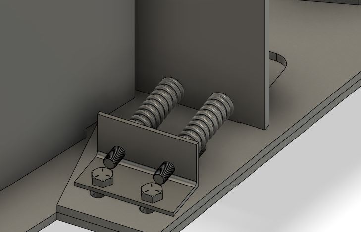
The design calls for the use of four pusher springs which ride on 5/16" guide bolts. These pusher springs push the turntable forward, away from two L-iron brackets anchored firmly to the deck. This mechanism allows for approximately 1.8" of eccentricity in the turntable circumference while applying around 200 lbs of force.
To install the pusher springs follow these instructions:
- Ensure that the Turntable Traction Drive is evenly supported and that you have strong material under the lag-bolt slots.
- Weld hex-heads the 5/16" partially-threaded guide bolts into the four holes provided in the pusher plates. The bolts should face backwards with the bolt heads resting on the interior faces of the pusher plates.
- Slide the pusher springs over the guide bolts.
- Pass the guide bolts into holes drilled in the L-iron.
- Using 5/16" lock nuts, compress the pusher springs between the L-Iron and the pusher plates.
- Using lag-bolts, bolt the L-iron to the supporting surface. Make sure the lag-bolts pass through the slots on the bottom plate.
- Loosen the 5/16" lock nuts such that the springs expand between staticaly mounted L-iron and the movable Turntable Traction Drive.
Note: In the pusher spring rendering there is insufficent clearance between the guide-bolts and the lag-bolts. This has been remedied by raising the holes in the pusher plate.
Integration Checklist
To help ensure safe operation of this Turntable Traction Drive please ensure the following REQUIRED conditions have been met:
| Requirement | Complete |
|---|---|
| Technical Director/Integrator must read and understand the safety section of this documentation. | |
| Turntable Traction Drive chassis grounded to motor frame | |
| Motor frame grounded to VFD | |
| Turntable Traction Drive is fully enclosed in a secure area | |
| Drive-wheel interface points are fully enclosed | |
| Turntable hard-scenery elements don't create opportunities for shearing or crushing | |
| Emergency stop button located within 6' of Turntable Traction Drive | |
| Turntable fitted with an external parking brake (or other disablement device.) |
VFD Configuration
DURApulse GS23-22P0 Configuration
Note: These notes are only really useful for the DURApulse GS23. If you're using another VFD consult your documentation.
When configured correctly we desire the following outcome:
- To tell the turntable to run forward short
DCMtoDI1/FWD. - To tell the turntable to run in revers short
DCMtoDI2/REV. - To enter Safe Torque Off
STOinterrupt short between+24 Vand eitherSTO1orSTO2
DURApulse GS23 Parameters
| Parameter | Value | Notes |
|---|---|---|
P02.00 |
2 |
2-Wire Configuration |
P01.10 |
60 |
Output Frequency Upper Limit |
P01.12 |
1 |
Acceleration Time 1 |
P01.13 |
1 |
Deceleration Time 1 |
P06.12 |
?? | Current Limit 0-250% |
Hitachi L100 Configuration
Note: These notes are only really useful for the Hitachi L-100. If you're using another VFD consult your documentation.
P24 provides a 24V field reference voltage for use when powering the Control Terminals.
When configured correctly we desire the following outcome:
- To tell the turntable to run forward short
P24toPIN 1. - To tell the turntable to run in revers short
P24toPIN 2.
Hitachi L100 Parameters
| Parameter | Value | Notes |
|---|---|---|
a01 |
00 |
00=Keypad/Potentiometer, 01=Control Terminals, 02=F01 Settings |
a02 |
02 |
01=Control Terminals, 02=Keypad Run Key |
a02 |
02 |
01=Control Terminals, 02=Keypad Run Key |
a61 |
60 |
Set a hard limit on the output frequency of the VFD to never overdrive the motor. |
a04 |
60 |
Set the "Base" Frequency. (The frequency at which the VFD emits full voltage) |
a05 |
60 |
Set the "Max" Frequency (The frequency allowed during manual opeation) |
a97 |
00 |
Set the Acceleration Curve: 00=Linear, 01=S-Curve |
a97 |
00 |
Set the Deceleration Curve: 00=Linear, 01=S-Curve |
c01 |
00 |
Configure Terminal 1: 00=Run Forward |
c02 |
01 |
Configure Terminal 2: 01=Run Reverse |
f01 |
nn |
Set the target frequency |
f02 |
nn |
Set the acceleration time (The number of seconds it should take to get spin-up from 0Hz to f01Hz) |
f03 |
nn |
Set the deceleration time (The number of seconds it should take to get spin-down from f01Hz to 0Hz) |
Turntable Traction Drive Operation Guide
This guide is designed to provide procedures for operating the Turntable Traction Drive.
![]() Before Proceeding, make sure you have read and understood the SAFETY section of the documentation.
Before Proceeding, make sure you have read and understood the SAFETY section of the documentation.
![]() Before Proceeding, make sure you have read and understood the Limitations section of the documentation.
Before Proceeding, make sure you have read and understood the Limitations section of the documentation.
Determining Safe Working Parameters
Once the Turntable Traction Drive has been integrated into your scenery you need to determine safe working values for the various parameters of your VFD.
In particular:
- Operating Frequency
- Acceleration Time
- Deceleration Time
- Current Limit
Operating Frequency
The operating frequency is the speed at which the drive motor runs. If a motor has a 60Hz native frequency then you should consider 60Hz to be 100% speed.
Determining a safe operating speed involves many factors and there may not be simple way to determine what's safe.
Observe the following:
- Always set an extremely slow Acceleration/Deceleration time when experimenting with speed.
- Always work your way up from a low speed to a high speed gradually.
Consider the following:
- Consider two people on a turntable may experiene different forces depending on their mass, height distance from the center.
- Consider that stepping on and off a moving turntable is dangerous and should be avoided.
- Consider that technicians working in proximity to a turntable may accidentally come into contact with it during shifts.
Acceleration/Deceleration
The Acceleration Time and Deceleration Time control how long it takes the drive to come up to full speed and how long it takes to slow down. Anytime that the motor is changing speed there is additional risk to on-stage personel, particularly when acceleration itself changes.
Observe the following:
- Avoid sub-second acceleration/deceleration times.
- Do not change acceleration/deceleration times without rehearsing under the new parameters.
Consider the following:
- Changing accelerations cause a "jerk" sensation. Where possible use linear acceleration parameters.
Current Limits
If your VFD permits it, consider setting as low a current limit as possible. This will allow your drive and motor to stall if your turntable meets unexpected resistance.
It may be neccesary to tune this parameter so that your VFD has suffient "starting torque" but will still stall if required.
Operations Checklist
Before each use the Turntable Traction Drive should be inspected to ensure that it is properly installed and safe to use.
| Checkpoint | Ready |
|---|---|
| Check machine/turntable pressure on left and right sides. | |
| Check to make sure drive-wheel is contacting the correct portion of the turntable on left and right sides. | |
| Check to make output-shaft sprockets have not slipped and are aligned with the power-sprockets. | |
| Visually inspect turntable circumference and remove any obstructions which may cause jamming. | |
| Remove parking brake (or disablement device) | |
| Connect controller to Drive | |
| Connect drive to power | |
| Test left and right rotation at performance speed. Listen for any unusual noises coming from the Turntable Traction Drive or the turntable itself. | |
| Test left and right rotation at performance speed. Watch for any unusual rubbing, slippage or stalling. | |
| Test local emergency stop button. |
Bill Of Materials
| Component | Units | Quantity | Unit Cost | Notes |
|---|---|---|---|---|
| Control | ||||
| Automation Direct DURApulse GS23-22P0* | EA | 1 | $208 | Variable Frequency Drive |
| Automation Direct GS20A-DR-AB | EA | 1 | $5 | VFD 35mm DIN rail adapter. |
| VFD Power Cable | EA | 1 | #10 3-Wire Appliance Cable | |
| VFD Power Connector | EA | 1 | NEMA 5-15P | |
| Control Pendant | EA | 1 | $36 | Compact Crane Control Pendant |
| Emergency Stop Buttons | PACK | 1 | $14 | Mushroom Cap E-Stop Buttons |
| Chassis | ||||
| Bottom Plate | EA | 1 | -- | Custom 1/4" Steel from BottomPlate-TotalSketch.dxf |
| Motor Gusset | EA | 1 | -- | Custom 1/4" Steel from MotorGusset-TotalSketch.dxf |
| Right Caster Gusset | EA | 1 | -- | Custom 1/4" Steel from RightCasterGusset-TotalSketch.dxf |
| Right Pusher Plate | EA | 1 | -- | Custom 1/4" Steel from RightPusherPlate-TotalSketch.dxf |
| Right Side Panel | EA | 1 | -- | Custom 1/4" Steel from RightSidePanel-TotalSketch.dxf |
| Left Caster Gusset | EA | 1 | -- | Custom 1/4" Steel from LeftCasterGusset-TotalSketch.dxf |
| Left Pusher Plate | EA | 1 | -- | Custom 1/4" Steel from LeftPusherPlate-TotalSketch.dxf |
| Left Side Panel | EA | 1 | -- | Custom 1/4" Steel from LeftSidePanel-TotalSketch.dxf |
| Front Plate | EA | 1 | -- | Custom 1/4" Steel from FrontPlate-TotalSketch.dxf |
| Top Plate | EA | 1 | -- | Custom 1/4" Steel from TopPlate-TotalSketch.dxf |
| Material, Plasma Cutting, Delivery | JOB | 1 | $811 | Custom Steel Cuttting to 1/16 Tolerance |
| Safety Label | JOB | 1 | -- | Custom Printed Vinyl Sticker from TurntableTractionDriveLabel.pdf |
| Input Side | ||||
| 3 Phase Electric Motor | EA | 1 | $600** | General Electric 2HP TEFC 5KE48WN8167 |
| Reduction Worm Gear | EA | 1 | $700*** | Morse 175Q140LR5 5:1 |
| Adjustable Motor-Mounting Base | EA | 1 | $40 | 62035K23 Fits NEMA 145 and NEMA 145T Frames |
| Roller Chain Sprocket 11 Teeth | EA | 2 | $17 | 6280K654 ANSI 40 Chain, 11 Teeth, for 7/8" Shaft Diameter |
| Motor Hold-Down Bolts | PACK | 1 | $7 | 92865A211 Medium-Strength Grade 5 Bolt, 3/8"-24 Thread, 1/2" Long |
| Motor Cable | EA | 1 | #10 4-Wire Appliance Cable | |
| Output Side | ||||
| Pillow Block Bearing | PACK | 1 | $5 | PGN - UCF204-12, Pack of 4 |
| Keyed Rotary Shaft | EA | 2 | $21 | 1497K116 - Fully Keyed, 3/4" Diameter, 9" Long |
| Keyed Drive Roller | EA | 2 | $118 | 61065K46 - 6" Roller Diameter, 3" Roller Width, for 3/4" Shaft Diameter |
| Roller Chain Sprocket 30 Teeth | EA | 2 | $68 | 6236K331 - ANSI 40 Chain, 30 Teeth, for 3/4" Shaft Diameter |
| Bearing Hold-Down Bolts | PACK | 1 | $15 | 92865A214 Medium-Strength Grade 5 Bolt, 3/8"-24 Thread, 7/8" Long |
| Spring Pusher | ||||
| 3" Pusher Spring | PACK | 1 | $13 | 9657K438 Compression Spring, 3" Long, 0.75" OD, 0.48" ID, Pack of 6 |
| Partially Threaded Spring Guide Bolts | PACK | 1 | $15 | 91247A126 Medium-Strength Grade 5 Bolt, 5/16"-24 Thread, 3-1/2" Long |
| Spring Guide Loading Nuts | PACK | 1 | $8 | 91247A128 Medium-Strength Grade 5 Nut, 5/16"-24 Thread |
| Miscelaneous | ||||
| Short Machine Key Steel | PACK | 1 | $3 | 98870A140 - 3/16" x 3/16", 1" Long, Undersized, Pack of 10 |
| Long Machine Key Steel | PACK | 1 | $9 | 98870A192 - 3/16" x 3/16", 3" Long, Undersized, Pack of 10 |
| #40 Roller Chain and Tools | PACK | 1 | $36 | 13 Pieces Roller Chain Disassembly Kit |
| 3/8-24 Drill and Tap Kit | EA | 2 | $10 | Drill America - POU3/8-24 3/8"-24 |
Total Cost Estimate: $2,980
* Choose a VFD that's compatible with your input power availability and which has a Safe Torque Off (STO) feature.
** Price Estimate. There are lots of different motors you can buy. The most important thing is that the power and form-factor be correct.
*** Price Estimate. There are lots of different gear reductions you can buy. Make sure you pick one that will fit the motor you're using when rotated 90 degrees.
Wiring Guide
For the sake of reusability we have wired our VFD into a semi-permanent control panel using DIN terminal blocks to connect the user wiring. This control panel is designed to be fully enclosed in scenery during use.
Be sure to follow the VFD manufacturer's specifications when selecing wiring materials. You don't want to under-spec the mains or motor wiring.
Wiring Guide (For Durapulse GS20)
| Terminal Number | End Point | Name |
|---|---|---|
| Input Side | ||
| G | VFD Ground | Ground |
TERMINAL1 |
L1 | Input Power Leg 1 |
TERMINAL2 |
L2 | Input Power Leg 2 |
TERMINAL3 |
L3 | Input Power Leg 3 |
| Output Side | ||
| G | VFD Ground | Ground |
TERMINAL4 |
T1 | Motor Turns 1 |
TERMINAL5 |
T2 | Motor Turns 2 |
TERMINAL6 |
T3 | Motor Turns 3 |
| Safety | ||
TERMINAL7 |
STO +24V | 24V Source For Safety Switches |
TERMINAL8 |
STO +24V | 24V Source For Safety Switches |
TERMINAL9 |
STO1 | Safety Input 1 |
TERMINAL10 |
STO2 | Safety Input 2 |
| Control | ||
TERMINAL11 |
DCM | Digital Control Common |
TERMINAL12 |
FWD | Forward Contactor |
TERMINAL13 |
REV | Reverse Contactor |
Control Wiring
| Wire | Pin | Terminal | Notes |
|---|---|---|---|
| Emergency Stop Button | 1 | TERMINAL9 |
STO disabled when shorted to +24VDC Source |
| Emergency Stop Button | 4 | TERMINAL7 |
STO +24VDC Source |
| Optional Second Emergency Stop Button | 1 | TERMINAL10 |
STO disabled when shorted to +24VDC Source |
| Optional Second Emergency Stop Button | 4 | TERMINAL8 |
STO +24VDC Source |
| Control Pendant | 1 | TERMINAL11 |
Voltage Sink for Digital Control |
| Control Pendant | 2 | TERMINAL13 |
REVERSE when shorted to votlage sink |
| Control Pendant | 3 | TERMINAL12 |
FORWARD when shorted to votlage sink |
Note: When not using the optional second emergency stop button you must have a jumper between TERMINAL8 and TERMINAL10.
License
Attribution 4.0 International

=======================================================================

Creative Commons Corporation ("Creative Commons") is not a law firm and
does not provide legal services or legal advice. Distribution of
Creative Commons public licenses does not create a lawyer-client or
other relationship. Creative Commons makes its licenses and related
information available on an "as-is" basis. Creative Commons gives no
warranties regarding its licenses, any material licensed under their
terms and conditions, or any related information. Creative Commons
disclaims all liability for damages resulting from their use to the
fullest extent possible.

Using Creative Commons Public Licenses

Creative Commons public licenses provide a standard set of terms and
conditions that creators and other rights holders may use to share
original works of authorship and other material subject to copyright
and certain other rights specified in the public license below. The
following considerations are for informational purposes only, are not
exhaustive, and do not form part of our licenses.

     Considerations for licensors: Our public licenses are
     intended for use by those authorized to give the public
     permission to use material in ways otherwise restricted by
     copyright and certain other rights. Our licenses are
     irrevocable. Licensors should read and understand the terms
     and conditions of the license they choose before applying it.
     Licensors should also secure all rights necessary before
     applying our licenses so that the public can reuse the
     material as expected. Licensors should clearly mark any
     material not subject to the license. This includes other CC-
     licensed material, or material used under an exception or
     limitation to copyright. More considerations for licensors:
	wiki.creativecommons.org/Considerations_for_licensors

     Considerations for the public: By using one of our public
     licenses, a licensor grants the public permission to use the
     licensed material under specified terms and conditions. If
     the licensor's permission is not necessary for any reason--for
     example, because of any applicable exception or limitation to
     copyright--then that use is not regulated by the license. Our
     licenses grant only permissions under copyright and certain
     other rights that a licensor has authority to grant. Use of
     the licensed material may still be restricted for other
     reasons, including because others have copyright or other
     rights in the material. A licensor may make special requests,
     such as asking that all changes be marked or described.
     Although not required by our licenses, you are encouraged to
     respect those requests where reasonable. More_considerations
     for the public:
	wiki.creativecommons.org/Considerations_for_licensees

=======================================================================

Creative Commons Attribution 4.0 International Public License

By exercising the Licensed Rights (defined below), You accept and agree
to be bound by the terms and conditions of this Creative Commons
Attribution 4.0 International Public License ("Public License"). To the
extent this Public License may be interpreted as a contract, You are
granted the Licensed Rights in consideration of Your acceptance of
these terms and conditions, and the Licensor grants You such rights in
consideration of benefits the Licensor receives from making the
Licensed Material available under these terms and conditions.


Section 1 -- Definitions.

  a. Adapted Material means material subject to Copyright and Similar
     Rights that is derived from or based upon the Licensed Material
     and in which the Licensed Material is translated, altered,
     arranged, transformed, or otherwise modified in a manner requiring
     permission under the Copyright and Similar Rights held by the
     Licensor. For purposes of this Public License, where the Licensed
     Material is a musical work, performance, or sound recording,
     Adapted Material is always produced where the Licensed Material is
     synched in timed relation with a moving image.

  b. Adapter's License means the license You apply to Your Copyright
     and Similar Rights in Your contributions to Adapted Material in
     accordance with the terms and conditions of this Public License.

  c. Copyright and Similar Rights means copyright and/or similar rights
     closely related to copyright including, without limitation,
     performance, broadcast, sound recording, and Sui Generis Database
     Rights, without regard to how the rights are labeled or
     categorized. For purposes of this Public License, the rights
     specified in Section 2(b)(1)-(2) are not Copyright and Similar
     Rights.

  d. Effective Technological Measures means those measures that, in the
     absence of proper authority, may not be circumvented under laws
     fulfilling obligations under Article 11 of the WIPO Copyright
     Treaty adopted on December 20, 1996, and/or similar international
     agreements.

  e. Exceptions and Limitations means fair use, fair dealing, and/or
     any other exception or limitation to Copyright and Similar Rights
     that applies to Your use of the Licensed Material.

  f. Licensed Material means the artistic or literary work, database,
     or other material to which the Licensor applied this Public
     License.

  g. Licensed Rights means the rights granted to You subject to the
     terms and conditions of this Public License, which are limited to
     all Copyright and Similar Rights that apply to Your use of the
     Licensed Material and that the Licensor has authority to license.

  h. Licensor means the individual(s) or entity(ies) granting rights
     under this Public License.

  i. Share means to provide material to the public by any means or
     process that requires permission under the Licensed Rights, such
     as reproduction, public display, public performance, distribution,
     dissemination, communication, or importation, and to make material
     available to the public including in ways that members of the
     public may access the material from a place and at a time
     individually chosen by them.

  j. Sui Generis Database Rights means rights other than copyright
     resulting from Directive 96/9/EC of the European Parliament and of
     the Council of 11 March 1996 on the legal protection of databases,
     as amended and/or succeeded, as well as other essentially
     equivalent rights anywhere in the world.

  k. You means the individual or entity exercising the Licensed Rights
     under this Public License. Your has a corresponding meaning.


Section 2 -- Scope.

  a. License grant.

       1. Subject to the terms and conditions of this Public License,
          the Licensor hereby grants You a worldwide, royalty-free,
          non-sublicensable, non-exclusive, irrevocable license to
          exercise the Licensed Rights in the Licensed Material to:

            a. reproduce and Share the Licensed Material, in whole or
               in part; and

            b. produce, reproduce, and Share Adapted Material.

       2. Exceptions and Limitations. For the avoidance of doubt, where
          Exceptions and Limitations apply to Your use, this Public
          License does not apply, and You do not need to comply with
          its terms and conditions.

       3. Term. The term of this Public License is specified in Section
          6(a).

       4. Media and formats; technical modifications allowed. The
          Licensor authorizes You to exercise the Licensed Rights in
          all media and formats whether now known or hereafter created,
          and to make technical modifications necessary to do so. The
          Licensor waives and/or agrees not to assert any right or
          authority to forbid You from making technical modifications
          necessary to exercise the Licensed Rights, including
          technical modifications necessary to circumvent Effective
          Technological Measures. For purposes of this Public License,
          simply making modifications authorized by this Section 2(a)
          (4) never produces Adapted Material.

       5. Downstream recipients.

            a. Offer from the Licensor -- Licensed Material. Every
               recipient of the Licensed Material automatically
               receives an offer from the Licensor to exercise the
               Licensed Rights under the terms and conditions of this
               Public License.

            b. No downstream restrictions. You may not offer or impose
               any additional or different terms or conditions on, or
               apply any Effective Technological Measures to, the
               Licensed Material if doing so restricts exercise of the
               Licensed Rights by any recipient of the Licensed
               Material.

       6. No endorsement. Nothing in this Public License constitutes or
          may be construed as permission to assert or imply that You
          are, or that Your use of the Licensed Material is, connected
          with, or sponsored, endorsed, or granted official status by,
          the Licensor or others designated to receive attribution as
          provided in Section 3(a)(1)(A)(i).

  b. Other rights.

       1. Moral rights, such as the right of integrity, are not
          licensed under this Public License, nor are publicity,
          privacy, and/or other similar personality rights; however, to
          the extent possible, the Licensor waives and/or agrees not to
          assert any such rights held by the Licensor to the limited
          extent necessary to allow You to exercise the Licensed
          Rights, but not otherwise.

       2. Patent and trademark rights are not licensed under this
          Public License.

       3. To the extent possible, the Licensor waives any right to
          collect royalties from You for the exercise of the Licensed
          Rights, whether directly or through a collecting society
          under any voluntary or waivable statutory or compulsory
          licensing scheme. In all other cases the Licensor expressly
          reserves any right to collect such royalties.


Section 3 -- License Conditions.

Your exercise of the Licensed Rights is expressly made subject to the
following conditions.

  a. Attribution.

       1. If You Share the Licensed Material (including in modified
          form), You must:

            a. retain the following if it is supplied by the Licensor
               with the Licensed Material:

                 i. identification of the creator(s) of the Licensed
                    Material and any others designated to receive
                    attribution, in any reasonable manner requested by
                    the Licensor (including by pseudonym if
                    designated);

                ii. a copyright notice;

               iii. a notice that refers to this Public License;

                iv. a notice that refers to the disclaimer of
                    warranties;

                 v. a URI or hyperlink to the Licensed Material to the
                    extent reasonably practicable;

            b. indicate if You modified the Licensed Material and
               retain an indication of any previous modifications; and

            c. indicate the Licensed Material is licensed under this
               Public License, and include the text of, or the URI or
               hyperlink to, this Public License.

       2. You may satisfy the conditions in Section 3(a)(1) in any
          reasonable manner based on the medium, means, and context in
          which You Share the Licensed Material. For example, it may be
          reasonable to satisfy the conditions by providing a URI or
          hyperlink to a resource that includes the required
          information.

       3. If requested by the Licensor, You must remove any of the
          information required by Section 3(a)(1)(A) to the extent
          reasonably practicable.

       4. If You Share Adapted Material You produce, the Adapter's
          License You apply must not prevent recipients of the Adapted
          Material from complying with this Public License.


Section 4 -- Sui Generis Database Rights.

Where the Licensed Rights include Sui Generis Database Rights that
apply to Your use of the Licensed Material:

  a. for the avoidance of doubt, Section 2(a)(1) grants You the right
     to extract, reuse, reproduce, and Share all or a substantial
     portion of the contents of the database;

  b. if You include all or a substantial portion of the database
     contents in a database in which You have Sui Generis Database
     Rights, then the database in which You have Sui Generis Database
     Rights (but not its individual contents) is Adapted Material; and

  c. You must comply with the conditions in Section 3(a) if You Share
     all or a substantial portion of the contents of the database.

For the avoidance of doubt, this Section 4 supplements and does not
replace Your obligations under this Public License where the Licensed
Rights include other Copyright and Similar Rights.


Section 5 -- Disclaimer of Warranties and Limitation of Liability.

  a. UNLESS OTHERWISE SEPARATELY UNDERTAKEN BY THE LICENSOR, TO THE
     EXTENT POSSIBLE, THE LICENSOR OFFERS THE LICENSED MATERIAL AS-IS
     AND AS-AVAILABLE, AND MAKES NO REPRESENTATIONS OR WARRANTIES OF
     ANY KIND CONCERNING THE LICENSED MATERIAL, WHETHER EXPRESS,
     IMPLIED, STATUTORY, OR OTHER. THIS INCLUDES, WITHOUT LIMITATION,
     WARRANTIES OF TITLE, MERCHANTABILITY, FITNESS FOR A PARTICULAR
     PURPOSE, NON-INFRINGEMENT, ABSENCE OF LATENT OR OTHER DEFECTS,
     ACCURACY, OR THE PRESENCE OR ABSENCE OF ERRORS, WHETHER OR NOT
     KNOWN OR DISCOVERABLE. WHERE DISCLAIMERS OF WARRANTIES ARE NOT
     ALLOWED IN FULL OR IN PART, THIS DISCLAIMER MAY NOT APPLY TO YOU.

  b. TO THE EXTENT POSSIBLE, IN NO EVENT WILL THE LICENSOR BE LIABLE
     TO YOU ON ANY LEGAL THEORY (INCLUDING, WITHOUT LIMITATION,
     NEGLIGENCE) OR OTHERWISE FOR ANY DIRECT, SPECIAL, INDIRECT,
     INCIDENTAL, CONSEQUENTIAL, PUNITIVE, EXEMPLARY, OR OTHER LOSSES,
     COSTS, EXPENSES, OR DAMAGES ARISING OUT OF THIS PUBLIC LICENSE OR
     USE OF THE LICENSED MATERIAL, EVEN IF THE LICENSOR HAS BEEN
     ADVISED OF THE POSSIBILITY OF SUCH LOSSES, COSTS, EXPENSES, OR
     DAMAGES. WHERE A LIMITATION OF LIABILITY IS NOT ALLOWED IN FULL OR
     IN PART, THIS LIMITATION MAY NOT APPLY TO YOU.

  c. The disclaimer of warranties and limitation of liability provided
     above shall be interpreted in a manner that, to the extent
     possible, most closely approximates an absolute disclaimer and
     waiver of all liability.


Section 6 -- Term and Termination.

  a. This Public License applies for the term of the Copyright and
     Similar Rights licensed here. However, if You fail to comply with
     this Public License, then Your rights under this Public License
     terminate automatically.

  b. Where Your right to use the Licensed Material has terminated under
     Section 6(a), it reinstates:

       1. automatically as of the date the violation is cured, provided
          it is cured within 30 days of Your discovery of the
          violation; or

       2. upon express reinstatement by the Licensor.

     For the avoidance of doubt, this Section 6(b) does not affect any
     right the Licensor may have to seek remedies for Your violations
     of this Public License.

  c. For the avoidance of doubt, the Licensor may also offer the
     Licensed Material under separate terms or conditions or stop
     distributing the Licensed Material at any time; however, doing so
     will not terminate this Public License.

  d. Sections 1, 5, 6, 7, and 8 survive termination of this Public
     License.


Section 7 -- Other Terms and Conditions.

  a. The Licensor shall not be bound by any additional or different
     terms or conditions communicated by You unless expressly agreed.

  b. Any arrangements, understandings, or agreements regarding the
     Licensed Material not stated herein are separate from and
     independent of the terms and conditions of this Public License.


Section 8 -- Interpretation.

  a. For the avoidance of doubt, this Public License does not, and
     shall not be interpreted to, reduce, limit, restrict, or impose
     conditions on any use of the Licensed Material that could lawfully
     be made without permission under this Public License.

  b. To the extent possible, if any provision of this Public License is
     deemed unenforceable, it shall be automatically reformed to the
     minimum extent necessary to make it enforceable. If the provision
     cannot be reformed, it shall be severed from this Public License
     without affecting the enforceability of the remaining terms and
     conditions.

  c. No term or condition of this Public License will be waived and no
     failure to comply consented to unless expressly agreed to by the
     Licensor.

  d. Nothing in this Public License constitutes or may be interpreted
     as a limitation upon, or waiver of, any privileges and immunities
     that apply to the Licensor or You, including from the legal
     processes of any jurisdiction or authority.


=======================================================================

Creative Commons is not a party to its public
licenses. Notwithstanding, Creative Commons may elect to apply one of
its public licenses to material it publishes and in those instances
will be considered the “Licensor.” The text of the Creative Commons
public licenses is dedicated to the public domain under the CC0 Public
Domain Dedication. Except for the limited purpose of indicating that
material is shared under a Creative Commons public license or as
otherwise permitted by the Creative Commons policies published at
creativecommons.org/policies, Creative Commons does not authorize the
use of the trademark "Creative Commons" or any other trademark or logo
of Creative Commons without its prior written consent including,
without limitation, in connection with any unauthorized modifications
to any of its public licenses or any other arrangements,
understandings, or agreements concerning use of licensed material. For
the avoidance of doubt, this paragraph does not form part of the
public licenses.

Creative Commons may be contacted at creativecommons.org.